

Busca de Produtos
PRODUTOS
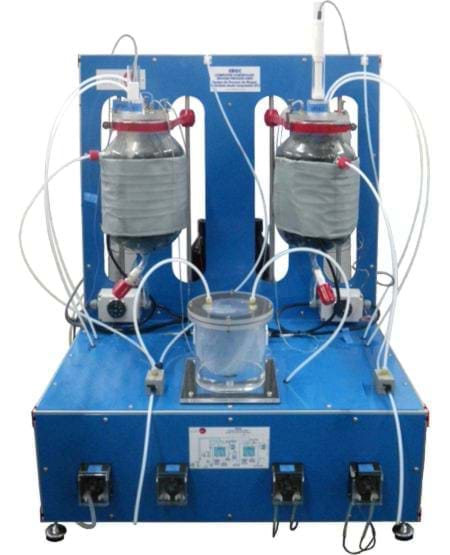
Computer Controlled Biogas Process
Cód. EBGC
PRINCIPAIS CARACTERÍSTICAS
The EBGC unit is designed to study and understand the different processes given during the biogas generation through anaerobic breakdown, as well as the study of the different parameters that affect the anaerobic digestion itself and the value of the obtained biogas.
Mais Detalhes do Produto
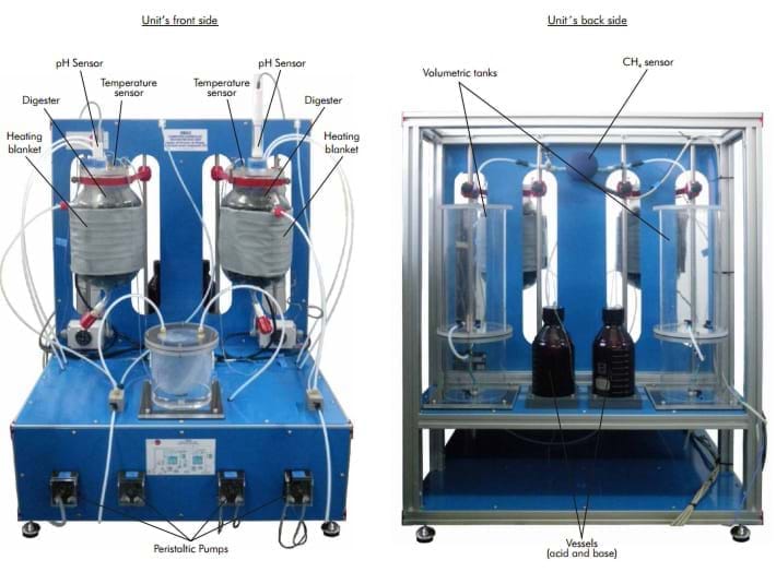
The unit is supplied with two packed anaerobic digesters. In this way, the user can work either in only one stage or in two stages, separating the different phases of the digestion process (the processes of hydrolysis, acidogenesis and acetogenesis would take place in the first digester, and the methanogenesis in the second digester).
Both digesters have a heating blanket that allows to regulate both the appropriate temperature for each part of the process and the operation with different ranges depending on the used microorganisms. Thus, it can operate at the psychrophilic range (room temperature), mesophilic range (temperatures around 35ºC) or thermophilic range (temperatures around 55ºC).
The unit has four peristaltic pumps which enable the propelling of both the supply to be introduced in the digester and the acid and the base (introduced in two vessels located at the rear side) in order to adjust and control thoroughly the pH in each stage of the process. In case of working in an anaerobic digestion in two stages, one of the pumps carries the product from one of the digesters to the other,passing through a buffer tank which collects the excess of flow from the first reactor. The control of these pumps allows to know the different flows with which the unit is working.
Two volumetric tanks are also included for the storage and volume measurement of the generated biogas.
The generated biogas flows through a pipe from the upper side of the digesters to these tanks, where the biogas volume is measured by means of a water displacement.
Such tanks have two parts: the upper side is where the generated biogas is collected and the second part, smaller than the first one and located below it, is used to collect the displaced water.
Each digester has a temperature sensor and a pH sensor. Their function is to follow the whole process and study the influence of the different controlling parameters in the anaerobic digestion.
Finally, the volumetric tanks, by their upper side, enable the flowing of the collected biogas through a pipe and its passing through a methane (CH ) sensor. This sensor allows to know the methane concentration in such current. This way, the biogas quality depending on 4 the physical-chemical conditions under which the anaerobic digestion is developed can be determined, as well as its value as a renewable energy source.
This Computer Controlled Unit is supplied with the EDIBON Computer Control System (SCADA), and includes: The unit itself + a Control Interface Box + a Data Acquisition Boar
COMPLETE TECHNICAL SPECIFICATIONS EBGC. Unit:
EBGC. Unit:
Anodized aluminium structure and panels in painted steel.
Main metallic elements in stainless steel.
Diagram in the front panel with similar distribution to the elements in the real unit.
2 Packed anaerobic digesters of 5 liters. Reactors packing: 25 mm. diameter bactoballs.
2 Heating blankets of 120W with a thermostat, and a temperature sensor to
control, together with the thermostat and with the computer (PID control), the
heating temperature. Temperature range: 0-90ºC.
4 Peristaltic pumps, 50 cc/min, computer controlled.
Feeding flows measurement by the pumps calibration.
2 Volumetric tanks for the storage and volume measurement of the generated biogas.
Buffer vessel, of 1 l. of capacity.
2 Pyrex vessels, of 1 l. of capacity, for the acid and the base.
Waste tank, of 12 l. capacity.
Methane sensor to measure its concentration in the generated biogas, 0-100%.
2 pH sensors.
2 Temperature sensors, “J” type.
EBGC/CIB. Control Interface Box:
The Control Interface Box is part of the SCADA system.
Control interface box with process diagram in the front panel and with the same distribution that the
different elements located in the unit, for an easy understanding by the student.
All sensors, with their respective signals, are properly manipulated from -10V. to +10V. computer output.
Sensors connectors in the interface have different pines numbers (from 2 to 16), to avoid connection errors.
Single cable between the control interface box and computer.
The unit control elements are permanently computer controlled, without necessity of changes or
connections during the whole process test procedure.
Simultaneous visualization in the computer of all parameters involved in the process.
Calibration of all sensors involved in the process.
Real time curves representation about system responses.
Storage of all the process data and results in a file.
Graphic representation, in real time, of all the process/system responses.
All the actuators’ values can be changed at any time from the keyboard allowing the analysis about
curves and responses of the whole process. All the actuators and sensors values and their responses are
displayed on only one screen in the computer. Shield and filtered signals to avoid external interferences.
Real time PID control with flexibility of modifications from the computer keyboard of the PID
parameters, at any moment during the process. Real time PID and on/off control for pumps, compressors,
resistances, control valves, etc. Real time PID control for parameters involved in the process
simultaneously. Proportional control, integral control and derivative control, based on the real PID
mathematical formula, by changing the values, at any time, of the three control constants (proportional,
integral and derivative constants).
Open control allowing modifications, at any moment and in real time, of parameters involved in the
process simultaneously.
Possibility of automatization of the actuators involved in the process.
Three safety levels, one mechanical in the unit, another electronic in the control interface and the
third one in the control software.
The complete unit includes as well:
Advanced Real Time SCADA and PID Control.
Open Control + Multicontrol + Real Time Control.
Own Control Software based on Labview.
National Instruments Data Acquisition board (250 KS/s (kilo samples per second)).
Calibration exercises included.
Students multipost (an entire class) by using a projector.
Ready for doing applied research, real industrial simulation, training courses possibilities, etc.
Unit is totally safe (Mechanical, Electronic/Electrical and Software safety devices included).
Results calculation and analysis software (CAL).
Several future expansions, as ESN. EDIBON Scada-Net System (many students working
simultaneously), and more.
Designed and manufactured under several quality standards.